The Celtic Peasant is building an analog synthesizer keyboard controller to be used with the Electronic Peasant's SynthCase projects.
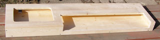
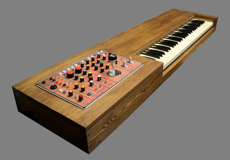
First an old organ, with two 3 1/2 Octave keyboards, was purchased for $25.00. The organ was broken down and the keyboards were salvaged for this project. The next step was to remove all wiring from the assembly and clean all of the keys. Once I had that completed I sawed through the metal and wooden supports to create a 5 octave keyboard. Here is the final result:
With the keyboard ready I populated the pcbs that I am using in the controller - Ray Wilson's Single Bus Keyboard Controller and the Oscillator Driver section of Juergen Haible's Living VCO pcb.
We are combining the two boards and adding additional features. The next step is to breadboard the circuit (a first for me) under the tutelage of The Peasant. Using the modified schematic, the population of the pcbs above will proceed and I will be using perfboard to complete the new design (another first for me). Pictures of all of the populated boards will be provided once the construction process is further along.
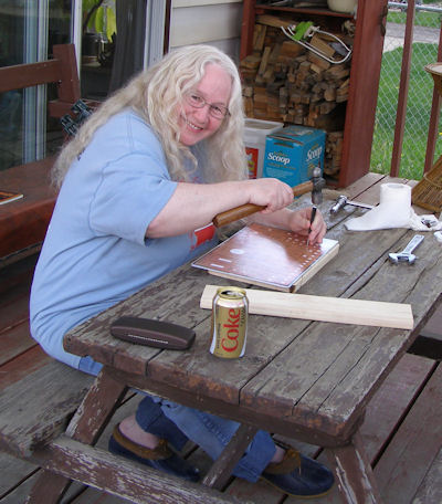
For the keyboard itself I had to match 67 100R resistors to .05% (I matched a few more than I needed to be on the safe side). They will not be soldered to the key connections until the keyboard itself is mounted in the case.
Both the casing for the keyboard and the control panel have been designed. The wood has been purchased and is ready to be cut to size and assembled.
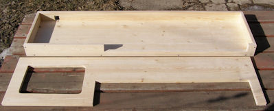
The pieces for the case were cut to size and the sanding began.
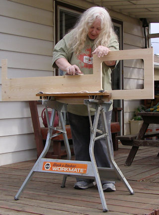
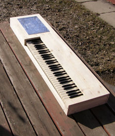
With the sanding done the two major pieces were placed together to ensure they fit - final sanding was done at this point and then the metal backing for the panel and the keyboards were placed in to check and see that everything else was fitting as it should.
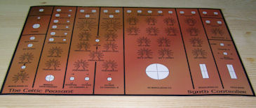
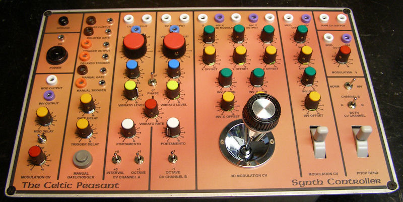
The panel graphics were completed and sent to the printer. We were excited to see they came out exactly as we hoped
and one last look at all the woodworking and graphics together so we could pick out a stain - which turned out to be a process of mixing two stains together until we achieved the exact color we wanted.
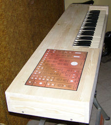
The staining and some finishing touches have been done and will be seen a little later in this project page.
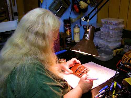
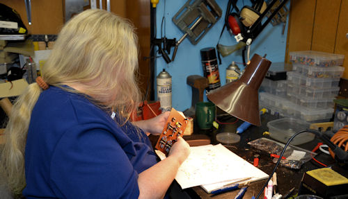
Now on to the fun times ... breadboarding! My first experience with that, guided by the designer of the joy stick control portion, The Electronic Peasant, has just been completed.
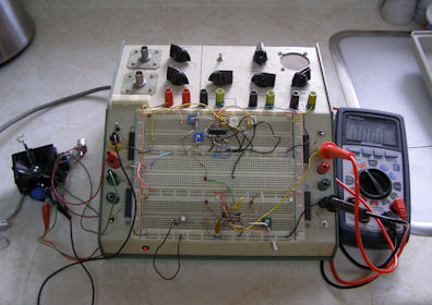
Now that it has been determined that the design is working, the schematics are being drawn up. There will still be a little more breadboarding needed for the additions to the existing boards, so that will be done next. After that I will be drilling the holes for the parts to be placed in the control panel.
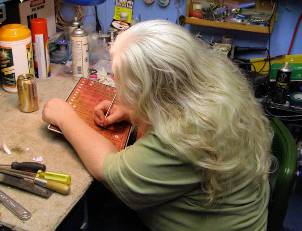
In order to drill the holes, I first had to carefully place the graphics sheet on the metal panel, secure them together with tape and use a Center Punch to mark the location of each hole to be drilled.
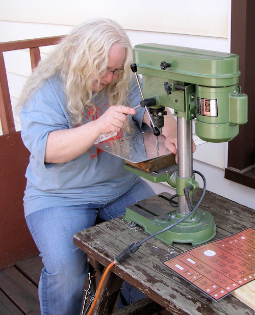
The punching has been completed ....

and now I am ready to drill. The holes were drilled according to the size required for each particular type of part. Some holes had to be filed a little larger. The large rectangular holes for the mod wheels required extensive filing. It was nice to bring the drillpress up from our workshop and work on this outside.
The holes have been completed and standoffs attached for mounting the mod wheels. The front of the panel was then filed so that the graphics sheet would have an even surface to attach to.
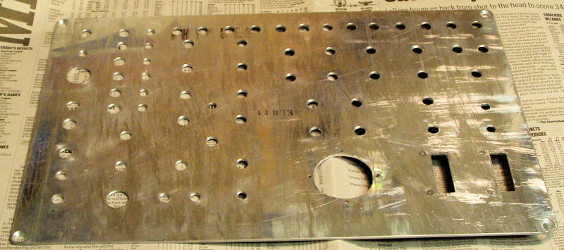
After the graphics sheet was glued onto the panel each hole was trimmed to size with a sharp knife.
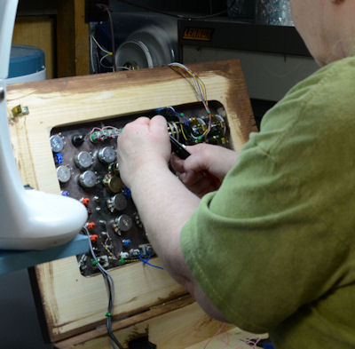
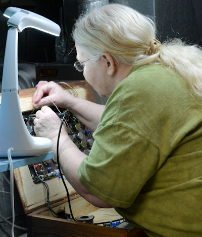
Putting the parts onto the panel was rewarding and entailed alot more planning and detail than I expected. I learned the importance of placement of the parts keeping the wiring in mind and juggling to ensure no parts would be rubbing against the panel, especially in the case of the mod wheels.
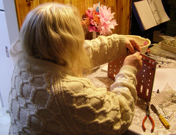
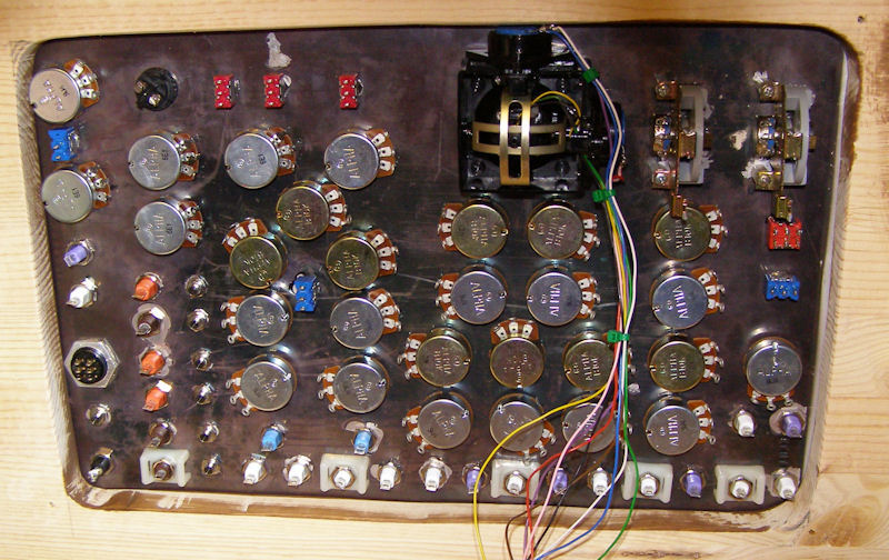
Banana jacks, LED bezels, switches, knobs and wheels all mounted, the last item was the joystick. The joystick had to be taken apart so that it could be mounted. Before mounting it I soldered wires to the pots as they would be hard to access once installed. The Electronic Peasant helped with the wiring of the Z-axis as that was little advanced for me at the moment.
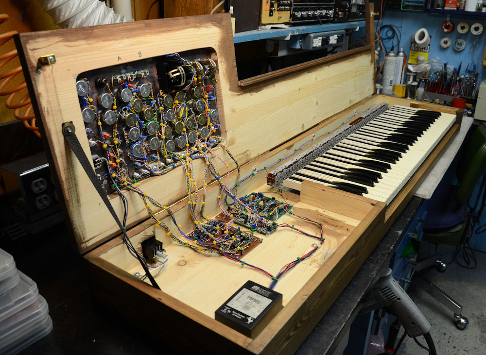
Then I mounted the completed panel onto the top of the keyboard case.
Stripboarding turned out to be one of my favourite parts of the process to this point! Working from the schematic and the challenge of populating the board ... fitting everything in, was very satisfying.
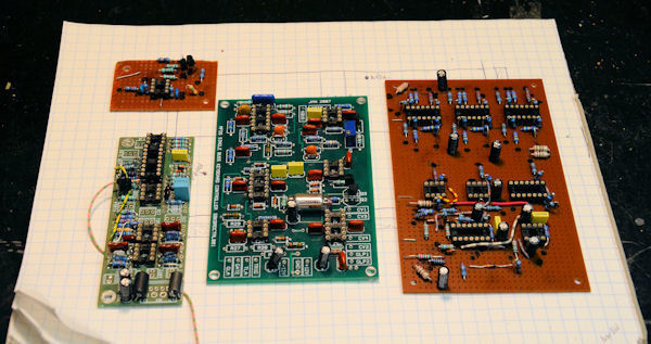
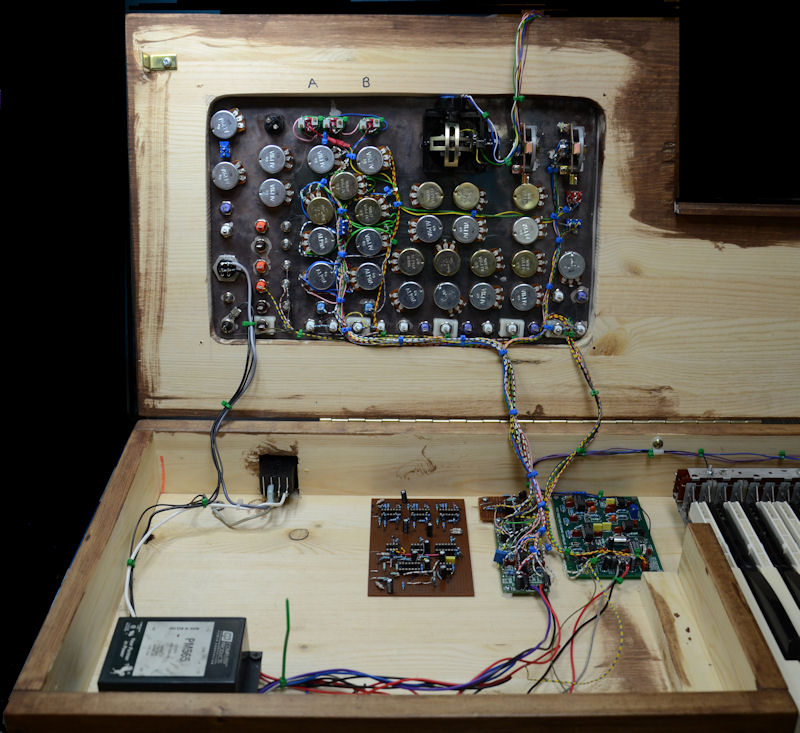
All the boards are now populated! The larger stripboard contains the circuitry for the Joystick and other CV modulation sources.
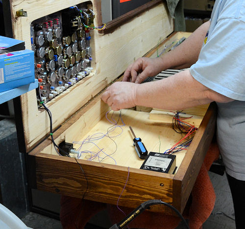
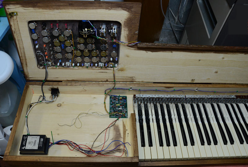
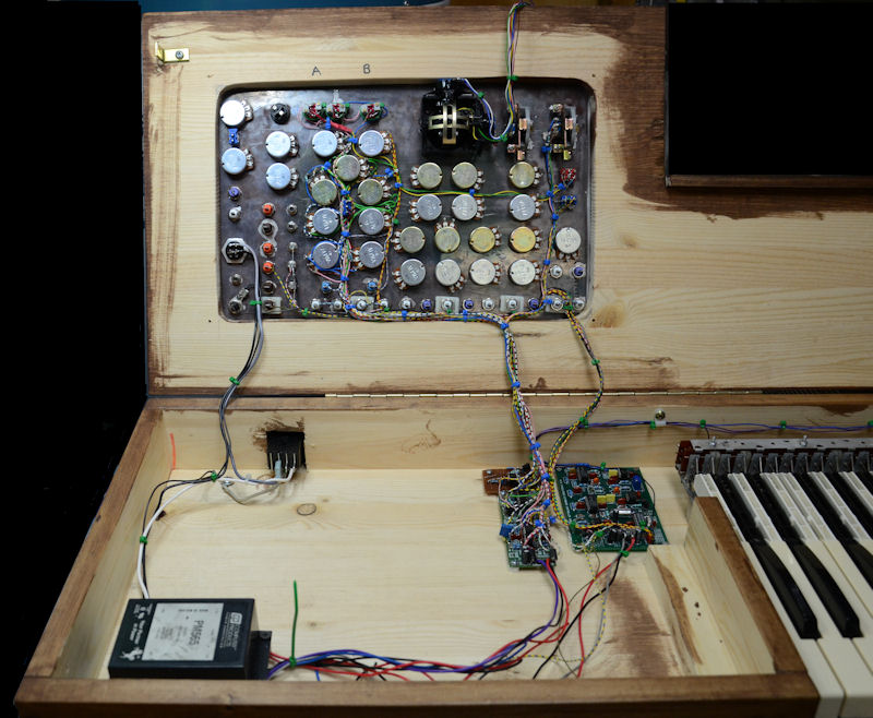
The next step was to mount the keyboard in place, install the hinges that attach the top cover to the case, wire in the power entry module,
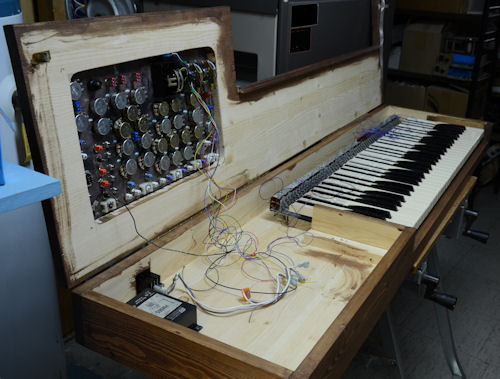
connect the wiring to the keys and connect the AC wiring to the power supply.
The heart of the keyboard circuitry, MFOS Volt-Per-Octave PCB, was the first board to be wired in.
Then came the testing. I was looking forward to my first trouble shooting, but other than two stuck keys everything worked just like it should.
Testing complete, the board was mounted into place!
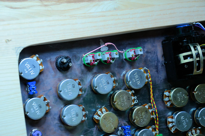
Trimmer Potentiometers were attached to the Octave and Interval switches.
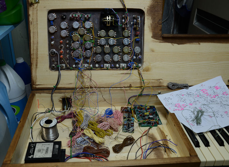
The next step was to wire up the two separate CV channels using the Oscillator Driver section from JH's Living VCO PCB. This board was modified by the Electronic Peasant to contain additional circuitry required for the second channel.
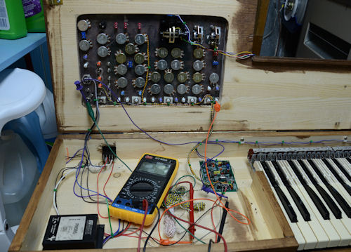
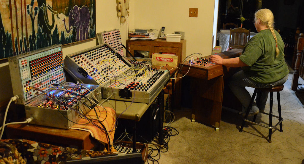
With the all of the note CV circuitry wiring completed I decided to patch the keyboard into The Peasants Synthcase system to see how it performed. It was exciting to 'hear' the results of my work -- the keyboard was in tune, everything worked!! Wow! I discovered that, by using the different CV channels with the Interval and Octave switches, I was able to mimic chords and change between them at the flick of a switch or two. After determining that all of the functions relating to the first two circuit boards were working correctly, the wires were ready to dress and the board could be secured to the case.
Now to wire up the last circuit board which contains all of the modulation circuitry as well as the trigger/gate delays and manual trig/gate.
Wiring has been completed and trouble shooting done. A few minor errors were corrected, some adjustments were made and a strap was added to support the lid at the correct angle when opened.
Being only my second project, the keyboard has exceeded my expectations. It was a very advanced project for my skill level, but with the help and support of The Peasant, I was able to create an exciting musical instrument. My soldering (and desoldering!!) skills improved immensely during the process. My understanding of circuitry including shortcuts and fixes has increased more than I thought I could possibly learn and understand during this past year. Just a few months ago stripping wire was something that was a challenge, now I can do it with ease. Now ... the exciting process of making music and learning to use The Electronic Peasant's SynthCase system.
Now on to my next project .... !